+86-577-62627101
- Home
- About us
-
Proudct
- DR series is economical din rail type switching power supply
- MDR series is economical din rail type switching power supply with signal output function
- NDR series is economical din rail type switching power supply
- EDR series is economical din rail type switching power supply
- LP series is din rail type switching power supply with output voltage digtal display
- NLP series is small size din rail type switching power supply
- HDR series is ultra-slim step sharp din rail switching power supply
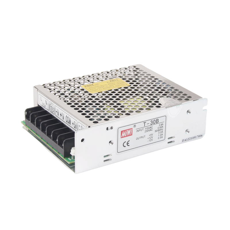
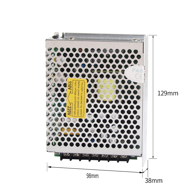
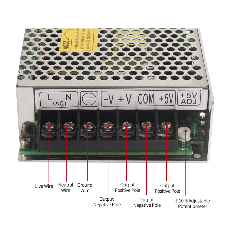
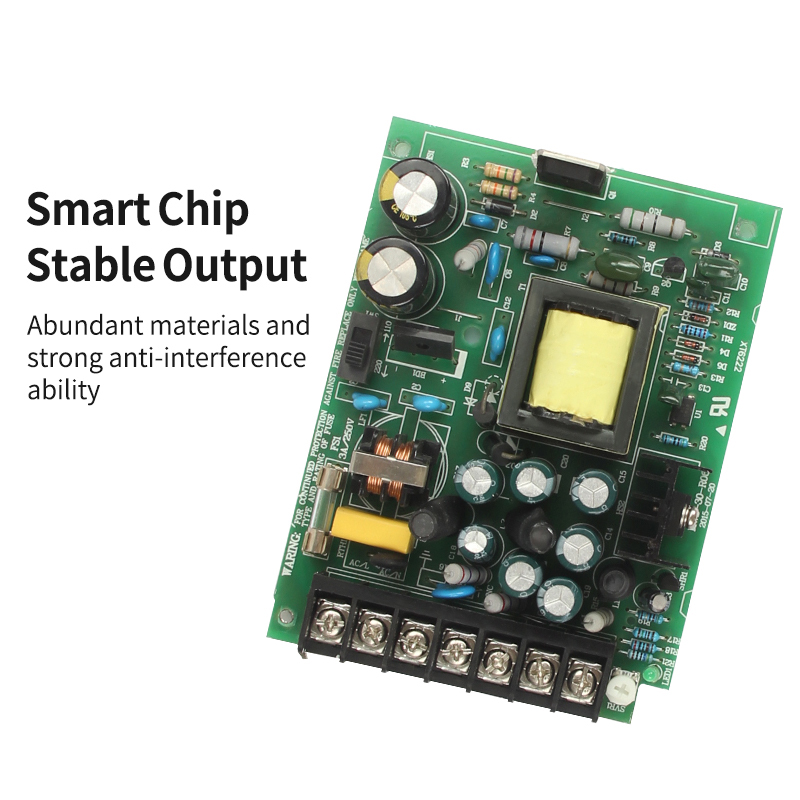
- S series is regular switching power supply
- View More
- Application
- Service
- News
- Contact us
- 中文